At Dongguan Precision Test Equipment Co., Ltd., our commitment extends beyond providing top-quality vibration test equipment. We are dedicated to ensuring our customers experience the highest level of satisfaction through comprehensive after-sales service. This includes expert maintenance, efficient repair, and valuable upgrade services for a wide range of vibration testing systems.
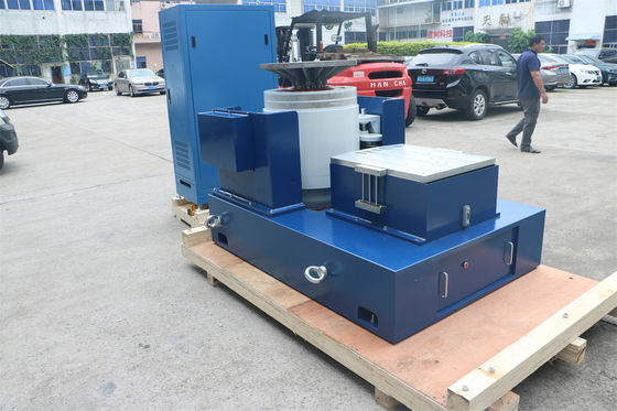
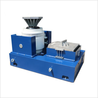
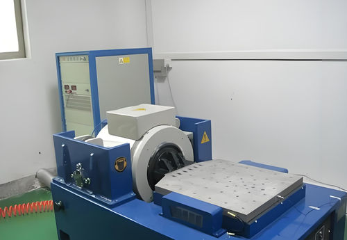
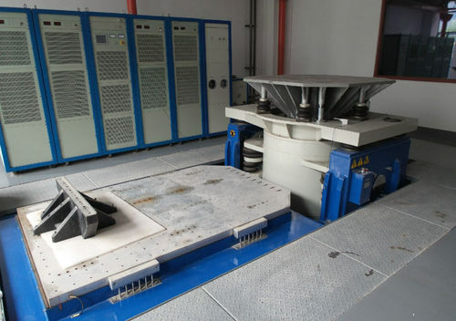
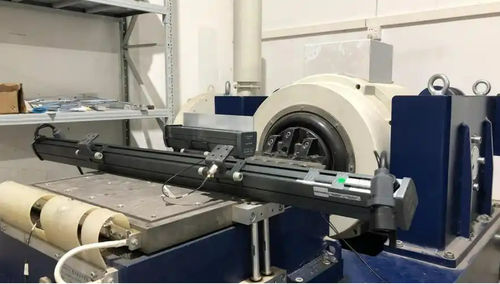
As a high-tech enterprise specializing in the manufacturing of electrodynamic shakers, hydraulic shakers, power amplifiers, and vibration controllers – and proud to be the first domestic company with in-house R&D and production of these three core components – our products are trusted by leading enterprises, testing laboratories, and universities both domestically and internationally. Our reach extends to Russia, North America, Japan, the Middle East, and beyond.
With over a decade of dedicated effort, we have evolved into a comprehensive technology company integrating R&D, production, sales, and, crucially, service. Our experienced after-sales team is equipped to provide professional maintenance, repair, and upgrade services for various renowned international brands such as LDS (UK), UD (USA), LING (USA), TIRA (Germany), B&K (Denmark), IMV (Japan), SHINKEN (Japan), and KOKUSAI (Japan), as well as domestic brands of vibration shakers, power amplifiers, and vibration controllers.
Our Comprehensive Service Offerings:
We understand the critical role vibration test systems play in your operations. Our services are designed to minimize downtime, maximize equipment lifespan, and ensure optimal performance.
Vibration Shaker Services:
Armature Maintenance, Repair, and Replacement: Expert care for the core moving component of your shaker, ensuring its integrity and performance.
Excitation Coil Maintenance, Repair, and Replacement: Addressing issues with the electromagnetic heart of the shaker.
Wear Part Replacement: Timely replacement of consumable components such as PP pull plates, lower guide wheels, dust boots, fuses, anti-wear hydraulic oil, air hoses, and fan ducts.
Horizontal Slip Table Maintenance, Repair, and Replacement: Ensuring smooth and accurate horizontal vibration testing.
Sensor Cable and BNC Cable Replacement: Addressing signal transmission issues with high-quality replacements.
Head Expander Options: Providing solutions to accommodate larger test specimens.
Comprehensive Mechanical Maintenance: Overall servicing of the shaker's mechanical components for optimal operation.
Power Amplifier Services (Electrical Aspects):
Power Amplifier Module Maintenance, Repair, and Replacement: Addressing issues at the component level for efficient power delivery.
Power Amplifier Control Module Maintenance, Repair, and Replacement: Ensuring the proper functioning of the amplifier's control electronics.
Comprehensive Electrical Maintenance: Overall servicing of the amplifier's electrical systems for reliable performance.
Vibration Controller Services:
Channel Bias Calibration and Dust Removal: Maintaining the accuracy and longevity of your controller's input channels.
Troubleshooting Input, Communication, Output, and Power Faults: Efficient diagnosis and resolution of controller malfunctions.
Software Feature Additions and Hardware Upgrades/Replacements: Enhancing the capabilities and extending the lifespan of your controller.
Our Commitment to Customer Satisfaction:
Our core principle is to provide the most satisfactory products and services to our valued customers. We are dedicated to troubleshooting equipment failures, replacing faulty components, and offering software upgrades. Furthermore, we emphasize the importance of proactive maintenance. By developing and diligently executing scientific periodic maintenance plans, we play a crucial role in preventing potential issues and ensuring the continuous operation of your vibration test systems. We possess the extensive engineering capabilities for system inspection, maintenance, and rapid fault handling. Leveraging our brand strength and robust technical expertise, we are committed to delivering superior service.
Why Choose Dongguan Precision for Your Service Needs?
Experienced Professionals: Our after-sales team comprises seasoned technical service professionals with over 20 years of experience in the vibration testing industry, specializing in the maintenance and repair of various brands of vibration test equipment.
Rapid Response: We understand the urgency of minimizing downtime. We offer online responses within 30 minutes, arrange on-site service within 2 hours, and aim to reach your location within 24 hours.
Efficient Service Quality: Our service personnel prioritize your production needs, utilizing their extensive experience and scientific methods to quickly diagnose and resolve common failure causes.
Our Service Offerings in Detail:
Repair Services: When your equipment malfunctions, contact us promptly. We will arrange for a professional technical service engineer to provide online diagnostics within 30 minutes. Once the issue is identified, we will dispatch a technician for on-site repair and component replacement.
Maintenance and Upkeep Services: We develop scientific periodic maintenance plans, including the regular replacement of wear parts and provide expert guidance on the optimal daily use of your equipment.
Software Upgrade Services: Stay ahead with our software upgrade and feature enhancement support.
Trust Dongguan Precision to keep your vibration test systems operating at peak performance, ensuring the reliability and accuracy of your testing processes. Contact our service team today to discuss your maintenance, repair, or upgrade needs.
Encountering error messages like "Open Loop," "Drive Max," or "Gain Limit" during vibration testing can halt your progress and cause frustration. At Dongguan Precision Test Equipment Co., Ltd., we understand the importance of swift troubleshooting. This guide outlines seven key steps you can take to diagnose and resolve these common issues before escalating to more complex investigations.
When your vibration control software flags these errors, it typically indicates a mismatch between the commanded output and the system's ability to achieve it. Follow these steps to systematically identify the root cause:
Seven Steps to Troubleshoot "Open Loop," "Drive Max," and "Gain Limit" Errors:
1. Verify Power Amplifier Gain:
Check: Ensure that the gain control on your power amplifier is properly adjusted (i.e., turned up sufficiently). If the gain is set too low, the amplifier might not be providing enough power to drive the shaker to the desired levels.
Action: Gradually increase the gain on the power amplifier. Refer to your system's manual for recommended starting gain settings. Be cautious not to increase it excessively, which could lead to overdriving the shaker.
2. Inspect Interconnecting Cables:
Check: Thoroughly examine all cables connecting the vibration controller, the vibration shaker (vibration table), and the power amplifier.
Action: Ensure that all cables are securely plugged into the correct ports at both ends. Loose or incorrect connections are a common cause of signal loss or improper communication within the system. Pay close attention to the drive signal cable from the controller to the amplifier and the feedback signal cable from the accelerometer to the controller.
3. Confirm Sensor Connection and Input Channel Configuration:
Check: Verify that the accelerometer (vibration sensor) is correctly connected to the appropriate input channel on the vibration controller.
Action: Double-check the physical connection of the sensor cable. Within the vibration control software, review the input channel settings for the accelerometer. Ensure that the coupling mode (e.g., AC, DC, IEPE) is correctly configured to match the type of accelerometer you are using. An incorrect coupling setting can prevent the controller from receiving a valid feedback signal.
4. Check for Sensor Signal:
Check: Determine if the accelerometer is actually outputting a signal.
Action: Utilize the "Test Preview" or "Monitor" function within your vibration control software to view the time-domain signal from the input channel connected to the accelerometer. While observing the software display, gently tap or apply a small vibration near the accelerometer. You should see a corresponding change in the time-domain signal if the sensor is functioning and properly connected. If there is no signal, the sensor itself, its cable, or the controller's input channel might be faulty.
5. Evaluate System Noise and Pre-Test Level:
Check: Analyze the system noise floor and compare it to the initial output level of your test.
Action: During the "Test Preview," observe the RMS (Root Mean Square) value of the system noise on the input channel. Then, check the pre-test level setting in your target spectrum or test profile (often a default of 10%). If the pre-test level is less than twice the RMS noise value, the controller might struggle to establish a stable control loop due to the low signal-to-noise ratio.
Solution: Increase the pre-test level in the software settings to a value significantly higher (at least twice) than the measured system noise RMS. This provides the controller with a stronger initial signal to work with.
6. Perform Controller-Amplifier Loopback Test:
Check: Test the integrity of the signal path from the controller's drive output channel to the power amplifier.
Action: Temporarily disconnect the cable that normally runs from the controller's drive output to the power amplifier's input. Connect this same cable directly from the controller's drive output channel to one of the controller's input channels (the same type you use for your accelerometer feedback). Configure a simple closed-loop test in the software using this input channel as the feedback source. Run a low-level sine sweep or fixed frequency test. If this self-closed-loop test operates normally, it indicates that the controller's output and input channels, as well as the connecting cable, are likely functioning correctly. This helps isolate potential issues with the power amplifier or the connection between the amplifier and the shaker. Remember to reconnect the cables to their original configuration after this test.
7. Review Target Spectrum Level, Amplifier Gain, and Drive Limits:
Check: If the "Drive Max" error persists after checking the physical connections and sensor functionality, examine the software settings related to the desired output level and the amplifier's gain.
Action:
Target Spectrum Level: Ensure that the overall amplitude or level defined in your target spectrum (for random or shock tests) or the programmed amplitude (for sine tests) is not excessively high, demanding more output than the system can deliver with the current amplifier gain setting. Reduce the target level if necessary.
Amplifier Gain: Re-evaluate the power amplifier's gain setting. If the target spectrum level is high, you might need to increase the amplifier gain to provide sufficient drive signal.
Software Drive Limits: Check the "Drive Limit" settings within your vibration control software. These settings prevent the controller from sending an excessively large drive signal to the amplifier. If the drive limit is set too low, it might be prematurely restricting the output even if the amplifier has more headroom. Consider cautiously increasing the drive limit if necessary, while staying within the safe operating parameters of your system.
By systematically working through these seven steps, you can effectively troubleshoot common "Open Loop," "Drive Max," and "Gain Limit" errors in your vibration control software and get your vibration testing back on track. If the problem persists after these checks, it's recommended to consult the technical support team at Dongguan Precision for more in-depth assistance.
Encountering communication issues between your vibration controller and the operating computer can be a frustrating roadblock before initiating crucial vibration tests. If you're met with a "USB device not found" error message when launching your VCS vibration control software, don't worry. At Dongguan Precision Test Equipment Co., Ltd., we've compiled a straightforward troubleshooting guide to help you quickly identify and resolve the potential causes.
The primary communication link between the vibration controller and the computer is typically a USB 2.0 interface. When this connection fails, the software cannot recognize the controller hardware. Here are the common reasons behind this issue and how to address them:
Potential Causes and Solutions:
1. Physical USB Connection:
Reason: The most basic step is to ensure that the USB communication cable is physically connected securely between the vibration controller and the computer.
Solution: Carefully inspect both ends of the USB cable. Make sure they are firmly plugged into the designated USB ports on both the controller and the computer.
2. Loose USB Connectors:
Reason: Even if initially connected, the USB connectors at either end of the cable might have become loose or partially dislodged.
Solution: Gently wiggle the USB connectors at both the controller and computer ends. If there's any play, firmly push them in until they are securely seated. A loose connection can intermittently disrupt communication.
3. Controller Power Status:
Reason: The vibration controller needs to be powered on for the computer to recognize it as a connected device.
Solution: Check the power switch on your vibration controller. Ensure it is in the "ON" position. Look for any power indicator lights on the controller to confirm it's receiving power.
4. Missing or Incorrect Hardware Driver:
Reason: The computer requires specific hardware drivers (often labeled "USB 2.0 Device" or similar) to communicate with the vibration controller. If these drivers are not installed, outdated, or corrupted, the controller will not be recognized.
Solution:
Check Device Manager: Open the Device Manager on your computer (search for "Device Manager" in the Windows search bar). Look for any devices listed under "Universal Serial Bus controllers" or "Other devices" with a yellow exclamation mark or a question mark. This indicates a driver issue.
Reinstall Driver: If you find such an entry, right-click on it and select "Uninstall device." Then, unplug the USB cable from the computer, wait a few seconds, and plug it back in. Windows should attempt to automatically reinstall the driver.
Manual Installation: If automatic installation fails, you might need to manually install the driver from the software installation media that came with your vibration controller or download the latest driver from the manufacturer's website (e.g., Dongguan Precision's support section). Follow the installation instructions provided.
5. Interference from Virus Monitoring Software:
Reason: In some instances, overly aggressive virus monitoring software might mistakenly identify the hardware driver for the vibration controller as a potential threat and block its installation or operation.
Solution:
Temporarily Disable Virus Monitoring: As a troubleshooting step, temporarily disable your virus monitoring software.
Reinstall Driver: After disabling the software, try reinstalling the hardware driver for the USB 2.0 Device as described in point 4.
Whitelist Driver/Device: If the issue is resolved after disabling the antivirus, you'll need to configure your virus monitoring software to "whitelist" the vibration controller's hardware driver or the USB device itself to prevent future interference. Remember to re-enable your virus monitoring software after this step.
6. Faulty Computer USB Port:
Reason: The USB port on your computer that you are using to connect the vibration controller might be malfunctioning.
Solution:
Try a Different USB Port: Unplug the USB cable from the current port and try connecting it to a different USB port on your computer.
Reinstall Driver (with New Port): After connecting to a different port, allow Windows to attempt automatic driver installation. If it doesn't, manually reinstall the driver as outlined in point 4. This will help determine if the issue lies with a specific USB port.
By systematically checking these potential causes, you should be able to identify and resolve the "USB device not found" error and establish a successful connection with your vibration controller, allowing you to proceed with your crucial vibration testing. If you continue to experience issues after trying these steps, please don't hesitate to consult the technical support team at Dongguan Precision for further assistance.
In the realm of vibration testing, the accelerometer acts as the crucial sensory organ of your vibration test system. It's a transducer that converts the physical quantity of vibration (acceleration, and indirectly related to sound) into a measurable electrical signal, providing the essential input for analysis and control. At Dongguan Precision Test Equipment Co., Ltd., we emphasize the importance of proper accelerometer installation and usage for obtaining reliable and meaningful vibration data.
Accelerometers are the preferred choice for vibration measurement due to their advantageous characteristics, including:
Wide Dynamic Range: Capable of measuring both very small and very large vibration amplitudes.
Broad Frequency Range: Can accurately capture vibrations across a wide spectrum of frequencies.
Excellent Linearity: Provides a proportional electrical output to the input acceleration.
High Stability: Offers consistent and dependable measurements over time.
Relatively Convenient Installation: Can be mounted using various methods depending on the application.
To harness the full potential of your accelerometer and ensure accurate vibration measurements, adhere to the following installation principles and methods:
I. Installation Principles: Setting the Foundation for Accuracy
For optimal performance, observe these fundamental rules when installing your accelerometer:
a) Strategic Location: Position the accelerometer as close as possible to the specific test point of interest on the structure to ensure it experiences the same motion as the area being analyzed.
b) Secure and Firm Mounting: The accelerometer and its mounting surface must be as rigid and firmly connected as possible. The mounting surface should be clean and flat to ensure maximum contact and the most direct or shortest transmission path of the vibration. For uniaxial accelerometers, carefully align the sensing direction (main axis) with the direction of interest.
c) Minimizing Mass Loading Effects: The introduction of the accelerometer should cause minimal alteration to the test structure's motion. Employ symmetrical mounting techniques where possible to minimize motion distortion. The mass of the accelerometer and any mounting hardware should be significantly smaller than the dynamic mass of the measured structure (ideally a mass ratio of less than 1/10 for small, light objects).
d) Avoiding Resonance Interference: The maximum operating frequency of your test should be significantly lower than the mounting resonance frequency of the chosen accelerometer. Operating near the mounting resonance can lead to amplified and inaccurate readings.
e) Cable Management: When using axially connected accelerometers, stiff cables can induce strain on the housing, potentially affecting measurements. Securely clamp the cable close to the accelerometer to prevent this. For piezoelectric accelerometers, loose cables can generate triboelectric noise (frictional static electricity).
(Diagram showing Axial Lead Accelerometer and Side Lead Accelerometer) (Caption for diagram: 1 - Do not subject to force, 2 - Connection surface of the vibrating body, 3 - Secure the cable to the vibrating surface)
f) Electrical Isolation: Accelerometers have varying electrical insulation properties. Some have built-in insulated bases, while others require insulated mounting screws and mica washers to prevent ground loops in the measurement system. Using insulated screws with mica washers at the contact points is an effective way to resolve ground loop issues.
II. Specific Installation Methods: Practical Application
Here's a breakdown of common accelerometer installation methods:
a. Screw Mounting:
(Diagram showing a typical frequency response curve for a screw-mounted accelerometer with grease) (Caption for diagram: Typical frequency response curve of an accelerometer screw-mounted with grease (relative to the absolute acceleration of the structure at the connection point))
Surface Preparation: The mounting surface on both the accelerometer and the test structure must be clean, flat, and smoothly machined, meeting the manufacturer's recommended specifications. The mounting screw hole should be perpendicular to the mounting surface.
Torque Application: Tighten the mounting screw to the manufacturer's recommended torque to achieve a secure connection without damaging the accelerometer.
Coupling Medium: Apply a thin layer of oil or grease between the mating surfaces to enhance contact and maximize stiffness, improving high-frequency response.
Screw Length: Ensure the screw does not bottom out in the tapped hole, as this can create a small gap between the mounting surfaces, reducing stiffness.
b. Adhesive Bonding:
This method is suitable when drilling holes in the test structure is not feasible, electrical isolation is required, or the mounting surface has insufficient flatness. Adhesive mounting screws (studs with threads on one end and a bonding platform on the other) are also commonly used.
(Diagram showing a typical frequency response curve for an adhesively bonded accelerometer) (Caption for diagram: Typical frequency response curve of an adhesively bonded accelerometer (relative to the absolute acceleration of the structure at the connection point))
Surface Cleaning: Clean the bonding surfaces according to the adhesive manufacturer's recommendations.
Thin Adhesive Layer: Apply the adhesive to form a thin film, which should ideally act as a rigid spring for optimal frequency response.
Adhesive Selection: Acrylic or thermosetting adhesives are often used. Avoid soft adhesives or those that retain significant flexibility after solvent evaporation, as they can lower the resonant frequency. Cyanoacrylate adhesives (super glue like 502) offer a wide frequency response but are not suitable for all applications and can contaminate screw threads. Before application, clean the mounting surface with a hydrocarbon solvent, keeping the solvent away from cables and connectors. Press the sensor firmly into the adhesive quickly to achieve a thin bond line. Temperature limitations of the adhesive must also be considered.
c. Mounting Devices:
Mounting devices, including electrically insulated screws, should be stiff, lightweight, have a small moment of inertia, and be structurally symmetrical about the sensing axis. Avoid using brackets whenever possible. If necessary, opt for small, rigid metal cubes securely mounted to the structure with machined surfaces and tapped holes for screw connection.
d. Other Mounting Methods:
Alternative mounting techniques include using a thin layer of solidified beeswax, double-sided adhesive tape, magnetic bases, quick-mount clamps, and vacuum mounting bases.
(Diagram showing a typical frequency response curve for a beeswax-mounted accelerometer) (Caption for diagram: Typical frequency response curve of an accelerometer mounted with a thin layer of beeswax (relative to the absolute acceleration of the structure at the connection point))
Beeswax Mounting: Suitable for room temperature applications with sensors weighing less than 100 grams. It's convenient but limits the operating temperature to below 40°C and is suitable for lower acceleration levels.
(Diagram showing a typical frequency response curve for a double-sided tape-mounted accelerometer) (Caption for diagram: Typical frequency response curve of an accelerometer mounted with double-sided tape)
Double-Sided Tape Mounting: Various types of double-sided tapes offer different operating temperatures and thicknesses. Choose a tape appropriate for your application.
(Diagram showing a typical frequency response curve for a magnetic base-mounted accelerometer) (Caption for diagram: Typical frequency response curve of an accelerometer mounted with a magnetic base)
Magnetic Base Mounting: Convenient for quick measurements on ferromagnetic surfaces but limits the maximum vibration level and measurement frequency. This method typically lowers the mounting resonance frequency to around 7 kHz, reducing the usable frequency range to about 2 kHz (around 1/3 of the mounting resonance). Magnetic bases also add significant mass and have limited holding force, typically suitable for accelerations below 200g.
III. Important Precautions: Ensuring Longevity and Data Integrity
Keep these crucial points in mind when handling and using accelerometers:
a) Gentle Removal: When dismounting sensors, gently cut any adhesive or beeswax from the side rather than pulling directly from the mounting surface, which can damage the sensor.
b) Direct Bonding Caution: Direct bonding of most accelerometers without proper consideration for removal and potential damage is generally not recommended.
c) Cable Security for Charge-Type Accelerometers: Ensure charge-type accelerometer cables are securely fixed. Movement, bending, or stretching of these cables during measurement can cause changes in local capacitance and charge between the conductor and shield, introducing significant noise. IEPE (Integrated Electronic Piezoelectric) accelerometers with built-in amplifiers are much less susceptible to cable noise.
d) Connector Integrity: When using multiple extension cables, ensure connectors are kept clean and free from dust, water, or conductive contaminants.
e) Mass Loading on Light Objects: For small and lightweight objects (e.g., small blades), carefully consider the mass loading effect of the accelerometer. Aim for a mass ratio of the accelerometer to the test object of less than 1/10.
f) Avoid Dropping: Never drop the sensor onto hard surfaces, as this can cause irreparable damage.
g) Temperature Limits: Always operate sensors within their specified temperature range to prevent damage and ensure accurate measurements.
By adhering to these installation guidelines and usage precautions, you can maximize the accuracy, reliability, and lifespan of your accelerometers, ensuring high-quality data for your vibration testing endeavors. At Dongguan Precision, we are dedicated to providing you with not only advanced vibration test systems but also the knowledge to utilize them effectively.
Maintaining Your Environmental Test Chamber: Ensuring Longevity and Reliable Results
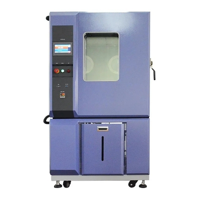
At Dongguan Precision Test Equipment Co., Ltd., we understand that your environmental test chamber is a crucial investment for ensuring the quality and reliability of your products. To maximize its lifespan, maintain testing accuracy, and prevent costly downtime, regular and proper maintenance is essential. This guide outlines key maintenance procedures for your environmental test chamber:
1. Dedicated and Professional Management:
For optimal care, we strongly recommend assigning dedicated, trained personnel to manage and maintain your test chamber. Where feasible, investing in professional training from the equipment supplier will equip your team with the specialized knowledge and skills needed for effective maintenance and troubleshooting.
2. Quarterly Condenser Cleaning:
Air-Cooled Systems: Regularly (every three months) inspect and clean the condenser fan. Remove any dust or debris buildup on the condenser fins to ensure proper airflow and efficient heat exchange for the compressor.
Water-Cooled Systems: In addition to maintaining the correct inlet water pressure and temperature, ensure the specified water flow rate is consistently provided. Crucially, schedule quarterly descaling and cleaning of the condenser's internal components to prevent scale buildup and maintain optimal heat transfer.
3. Quarterly Evaporator (Dehumidifier) Cleaning:
Due to the forced air circulation within the test chamber and the varying cleanliness levels of test samples, dust and particulate matter can accumulate on the evaporator (dehumidifier coils). A regular cleaning schedule (every three months) is vital to maintain efficient heat exchange for cooling and dehumidification.
4. Circulation Fan Blades and Condenser Fan Cleaning & Balancing:
Similar to the evaporator, the circulation fan blades and condenser fan blades can accumulate dust and debris depending on the chamber's operating environment. Regular cleaning is necessary to ensure proper airflow. Additionally, periodically check for any imbalance in the fan blades, which can lead to vibration and potential damage.
5. Maintaining an Optimal Ambient Environment:
Environmental test chambers are precision instruments and often represent a significant investment. To promote their longevity and stable operation, we recommend placing them in a controlled ambient temperature environment, ideally between 8℃ and 23℃. For laboratories that cannot meet these conditions, installing appropriate air conditioning (for air-cooled units) or a cooling tower (for water-cooled units) is strongly advised.
6. Water Circuit and Humidifier Cleaning:
A restricted water flow or scale buildup in the humidifier can lead to dry-burning and potential damage to the heating element. Therefore, it is imperative to regularly clean the water lines and the humidifier to ensure unobstructed water supply and efficient humidification.
7. Post-Test Routine:
Adopting a consistent post-test procedure is a simple yet effective maintenance practice. After each test completion, set the chamber temperature to near ambient conditions and allow it to run for approximately 30 minutes before powering it off. Finally, wipe down the interior walls of the workspace to remove any residual moisture or contaminants.
8. Troubleshooting Principles:
Environmental test chambers are complex systems comprising electrical, refrigeration, and mechanical components. When a malfunction occurs, a systematic and comprehensive approach to troubleshooting is essential.
External to Internal: Begin by eliminating external factors such as cooling water supply and power supply issues.
Systematic Analysis: Once external factors are ruled out, adopt a system-based approach. Start with a high-level system breakdown and then delve into more specific components.
Logical Deduction: A reverse troubleshooting method can be effective. Begin by checking the electrical wiring diagrams for potential electrical system faults and then investigate the refrigeration system.
Caution Before Disassembly: Never attempt to blindly disassemble or replace components without a clear understanding of the fault. This can lead to further complications and unnecessary expenses.
9. Long-Term Inactivity Protocol:
If the test chamber is to be taken out of service for an extended period, we recommend powering it on for at least one hour every two weeks. This helps to circulate the internal fluids and prevent potential issues arising from prolonged inactivity.
10. Safe Relocation:
Relocating an environmental test chamber should ideally be performed under the guidance of our qualified technical personnel. This will minimize the risk of accidental damage or malfunction during the moving process.
By adhering to these maintenance guidelines, you can significantly extend the lifespan of your Dongguan Precision environmental test chamber, ensure the accuracy and reliability of your testing results, and ultimately protect your investment. For any specific maintenance inquiries or to schedule professional servicing, please do not hesitate to contact our dedicated support team.
At Dongguan Precision Test Equipment Co., Ltd., we understand the paramount importance of product safety and reliability across various industries. To help manufacturers ensure their products meet stringent quality standards and withstand real-world conditions, we offer a comprehensive range of environmental test chambers designed to comply with a multitude of international and national testing standards. This document serves as a guide to the key testing standards our equipment is built to meet, particularly focusing on the critical area of New Energy Battery Testing and other essential environmental simulations.
I. Powering the Future Safely: New Energy Battery Testing Standards
The safety and performance of new energy batteries are critical. Our test chambers are designed to facilitate testing according to the following key standards:
Mechanical Impact Testing:
UL 1642: Standard for Lithium Batteries - Mechanical Tests - Impact Test
UL 2054-2005: Household and Commercial Batteries - Mechanical Tests - Impact Test
UN 38.3: Recommendations on the Transport of Dangerous Goods - Manual of Tests and Criteria - Section 38.3 - Impact Test
GB/T 18287-2000: General Specification for Lithium-ion Batteries for Cellular Telephones - Heavy Object Impact Test
SJ/T 11169-1998: Standard for Lithium Batteries - Impact Test
YD 1268-2003: Safety Requirements and Test Methods for Lithium Batteries and Chargers for Mobile Communication Handsets - Impact Test
SJ/T 11170-1998: Safety Standard for Household and Commercial Batteries - Mechanical Tests - Impact Test
Crush (Squeeze) Testing:
GB/T 2900.11-1988: Safety Performance Inspection Specification for Lithium-ion Batteries for Miner's Lamps - Crushing
YD 1268-2003: Safety Requirements and Test Methods for Lithium Batteries and Chargers for Mobile Communication Handsets - Crush Resistance Performance
SJ/T 11169-1998: Standard for Lithium Batteries - Crush Test
UL 1642: Standard for Lithium Batteries - Compression Test
GB/T 8897.4-2002: Primary Batteries - Part 4: Safety of Lithium Batteries - Crushing
SJ/T 11170-1998: Safety Standard for Household and Commercial Batteries - Crushing
YDB 032-2009: Backup Lithium-ion Battery Packs for Communication Use - Resistance to Extrusion
UL 2054: Standard for Household and Commercial Batteries - Compression Test
QB/T 2502-2000: General Specification for Lithium-ion Rechargeable Batteries - Crushing (Internal Short Circuit) Test
Puncture (Nail Penetration) Testing:
GB/T 18332.2-2001: Nickel-metal Hydride Rechargeable Batteries for Electric Road Vehicles - Puncture Test
MT/T 1051-2007: Lithium-ion Batteries for Miner's Lamps - Nail Penetration Test
II. Simulating Diverse Climatic Conditions: High & Low Temperature and Humidity Testing
Our High and Low Temperature Test Chambers, Constant Temperature and Humidity Test Chambers, and High and Low Temperature Humidity Test Chambers are engineered to meet the requirements of the following standards, ensuring reliable performance evaluation under various climatic stresses:
GB/T 5170.5-2008
GB/T 10586-2006
GB/T 2423.1-2008 (Test A: Cold)
GB/T 2423.2-2008 (Test B: Dry Heat)
GB/T 2423.3-2006 (Test Ca: Steady State Damp Heat)
GB/T 2423.4-2008 (Test Db: Alternating Damp Heat)
III. Withstanding Rapid Temperature Changes: Thermal Shock Testing
Our Thermal Shock Test Chambers are designed to subject products to rapid and extreme temperature variations, adhering to and satisfying the requirements of the following standards:
GB/T 2423.1-2001: Environmental testing for electric and electronic products - Part 2: Test methods - Test A: Cold
GB/T 2423.2-2001: Environmental testing for electric and electronic products - Part 2: Test methods - Test B: Dry heat
GB/T 2423.22-1989: Environmental testing for electric and electronic products - Part 2: Test methods - Test N: Change of temperature
GJB 150.3-86: Environmental test methods for military equipment - Low temperature test
GJB 150.4-86: Environmental test methods for military equipment - High temperature test
GJB 150.5-86: Environmental test methods for military equipment - Temperature shock test
GJB 360.7-87: Test methods for electronic components - Method 405: Temperature shock test
GJB 367.2-87: Test methods for electronic equipment - 405 Temperature shock test
SJ/T 10187-91: Y73 series temperature cycling test chambers - Single chamber type
SJ/T 10186-91: Y73 series temperature cycling test chambers - Two chamber type
IEC 68-2-14: Environmental testing - Part 2: Tests - Test N: Change of temperature
GB/T 2424.13-2002: Environmental testing for electric and electronic products - Part 2: Test methods - Guidance for temperature cycling tests
GB/T 2423.22-2002: Environmental testing - Part 2: Test methods - Test N: Change of temperature
QC/T 17-92: General rules for weathering test of automotive parts
EIA 364-32: Thermal Shock (Temperature Cycling) Test Procedure for Electrical Connectors and Sockets Environmental Effects Assessment
IV. Accelerating Failure Analysis: Highly Accelerated Life Testing (HAST) Chambers
Our Highly Accelerated Life Testing (HAST) Chambers are designed to accelerate the aging process of products under controlled high temperature and high humidity conditions, complying with:
GB/T 5170.2-1996: Environmental testing equipment for electric and electronic products - Part 2: Temperature chambers
IEC 60068-2-66-1994: Environmental testing - Part 2-66: Tests - Test Cy: Damp heat, steady state, accelerated test primarily intended for components
V. Evaluating Resistance to Sunlight: Ultraviolet Weathering Test Chambers
Our Ultraviolet Weathering Test Chambers simulate the damaging effects of sunlight, rain, and dew to assess the durability of materials exposed to outdoor environments, meeting the requirements of standards such as:
ASTM G154: Standard Practice for Operating Fluorescent Ultraviolet (UV) Lamp Apparatus for Exposure of Nonmetallic Materials
ASTM D4587-91:
ISO 11507/4892-3: Plastics - Laboratory sources of light - Part 3: Fluorescent UV lamps
NE 927-6
ASTM G 153: Standard Practice for Operating Enclosed Carbon Arc Light Apparatus for Exposure of Nonmetallic Materials
ASTM D 4329: Standard Practice for Fluorescent UV Exposure of Plastics
ASTM D 4799: Standard Practice for Accelerated Weathering Test Conditions and Procedures for Bituminous Materials (Xenon Arc Method)
ASTM D 4587: Standard Practice for Conducting Determinations of Resistance to Industrial Fluids
SAE J 2020: Accelerated Exposure of Automotive Exterior Materials Using a Fluorescent UV and Condensation Apparatus
ISO 4892:
VI. Your Partner in Compliance and Reliability: Dongguan Precision
At Dongguan Precision Test Equipment Co., Ltd., we are committed to providing high-quality, reliable environmental test chambers that empower manufacturers to meet the stringent demands of various industries. Our equipment is designed with precision engineering and adheres to a wide array of national and international testing standards, ensuring the safety, performance, and longevity of your products.
Contact us today to discuss your specific testing requirements and discover how our comprehensive solutions can help you achieve compliance and build greater confidence in the reliability of your products.
I. Understanding Thermal Shock Testing for PCBs
Concept: Thermal shock testing, also known as temperature cycling or thermal resistance testing, simulates the rapid temperature changes or alternating high and low temperature environments that a product might experience during its lifecycle.
Principle: During these abrupt temperature shifts or alternating extremes, the various materials comprising a PCB – including the substrate, prepreg (PP), copper plating, and solder mask – undergo expansion and contraction. The resulting stress and differences in the Coefficient of Thermal Expansion (CTE) of these materials can lead to physical damage, degradation, and changes in electrical resistance within the PCB.
II. The Importance of Thermal Shock Testing for PCBs
Thermal shock testing plays a vital role throughout the lifecycle of a PCB:
Early Design Flaw Detection (R&D Stage): Identifying and rectifying design weaknesses in the PCB at the research and development stage prevents costly issues later. This shortens the development cycle and reduces overall expenses.
Quality Control in Manufacturing: Assessing whether the quality of manufactured PCBs meets customer requirements. Detecting manufacturing process defects early allows for timely investigation and improvement, ensuring the safety and quality of shipped products.
Material and Process Validation: Evaluating the reliability of base materials, solder masks, prepregs, and manufacturing processes to determine their suitability for the product's intended environment.
Material and Process Comparison: Comparing the thermal shock resistance of PCBs fabricated with different materials and processes to identify superior options.
III. Equipment Parameters
Our thermal shock chambers at Dongguan Precision are designed to deliver precise and reliable testing:
Parameter
Specification
Nominal Internal Volume
300L
Test Temperature Range
-70℃ ~ 200℃
Temperature Fluctuation
≤ 1℃
Temperature Deviation
±2℃ (≤150℃) / ±3℃ (>150℃)
Heating Rate (High Temp. Chamber)
≥ 11℃/min
Cooling Rate (Low Temp. Chamber)
≥ 5℃/min
Max. Sample Weight
10kg
IV. Case Studies: Real-World PCB Thermal Shock Testing
Case Study 1: High-Layer Count Test Board
A high-layer count test board underwent online thermal shock testing to verify the performance of the selected substrate material against customer specifications. The testing conditions and requirements were as follows:
Test Item
Test Conditions
Test Requirements
Thermal Shock (Online)
-55℃/15min, 125℃/15min, 1000 Cycles
1. Resistance Change Rate ≤ 5%
2. No delamination, board cracking, orbarrel cracking observed in cross-section analysis
Resistance change rate curve chart
Sectional view of Test Position 1 Sectional view of Test Position 3
Outcome: Post-testing, the resistance change rate at certain test points exceeded 5%. Cross-sectional analysis revealed through-hole copper barrel cracking. This indicated a potential weakness in the substrate material's ability to withstand the stress induced by repeated temperature extremes. The findings prompted a re-evaluation of the substrate material selection for this high-layer count application.
Case Study 2: Automotive Test Board
An automotive test board was subjected to thermal shock testing to validate the performance of the solder mask material against customer
requirements. The testing conditions and requirements were as follows:
Test Item
Test Conditions
Test Requirements
Thermal Shock Test
-40℃/15min, 125℃/15min, 500 Cycles
No solder mask blistering, delamination, or cracking observed
1. IPC-TM-650 2.6.7.1A Conformal Coating Thermal Shock Resistance
2. IPC-TM-650 2.6.7.2C Thermal Shock, Thermal Cycling and Continuity
3. IPC-TM-650 2.6.7.3 Solder Mask Thermal Shock Resistance
Observation diagram after the test
V. Common Thermal Shock Test Conditions
The specific test conditions for thermal shock testing vary depending on the application and industry standards. Here are some common examples:
Sample Type
Low Temperature (°C)
High Temperature (°C)
Dwell Time (min)
Cycles
Automotive
-40
125
15 / 30
500
-55
140
1000
-65
150
1500
High-Layer Count
-40
125
15 / 30
250
-55
125
500
High-Frequency
-40
125
15
500
Package Substrate
-55
150
30
1000
VI. Reference Standard Conditions (Printed Boards)
Item
Qualification
Quality Conformance/Acceptance Testing
Baking Conditions
(105~125)℃ / 6h
Reflow Soldering
6 times IR
Test Temperature (Low)
Negotiated between supplier and buyer
-40℃, -55℃ (default), -65℃
Test Temperature (High)
Negotiated between supplier and buyer
Min: Tg-10℃ (TMA) / Reflow Peak Temp -25℃ / 210℃
Sample Temperature Change Rate
> 10℃/min (both hot and cold transition)
> 1℃/S (both hot and cold transition)
Test Cycles
Negotiated between supplier and buyer
100
Resistance Change Rate
Negotiated between supplier and buyer
5%
VII. Reference Standard Conditions (Conformal Coating & Solder Mask)
Level
Low Temperature (°C)
High Temperature (°C)
Dwell Time (min)
Cycles
Remarks
1
-40
125
15
100
Default test condition when no requirement specified
2
-65
125
15
100
3
-65
250
15
100
Outcome: Microscopic examination after the test revealed cracking in the solder mask at the corners of the pads. This indicated insufficient flexibility or adhesion of the solder mask material to withstand the thermal stresses encountered in the automotive environment. The results led to an investigation into alternative solder mask materials with improved thermal shock resistance for this automotive application.
VIII. Conclusion: Partnering with Dongguan Precision for Reliable Thermal Shock Testing
The case studies highlight the critical role of thermal shock testing in identifying potential weaknesses in PCB materials and designs. At Dongguan Precision Test Equipment Co., Ltd., we are committed to providing high-performance thermal shock chambers and expert support to help our customers thoroughly evaluate the reliability of their PCBs. Our equipment is designed for accuracy, repeatability, and adherence to industry standards.
By understanding the principles of thermal shock testing and utilizing reliable equipment, manufacturers can proactively address potential issues, ensuring the long-term performance and durability of their electronic products. Contact Dongguan Precision today to discuss your specific PCB testing needs and discover how our solutions can benefit your quality assurance processes.